

sidfaber
on 17 November 2020

Introduction
Our simple ROS 2 talker and listener setup runs well on a single Kubernetes node, now let’s distribute it out across multiple computers. This article builds upon our simple ROS 2 talker / listener setup by running it on multiple K8s nodes.
At the completion of this setup expect to have a ROS2 Kubernetes cluster running MicroK8s on three different machines. Applying a single configuration file distributes the ROS 2 workload across the machines.
This is the third article in a series of four posts describing ROS 2 applications on Kubernetes with MicroK8s:
- Part 1: ROS 2 and Kubernetes basics
- Part 2: ROS 2 on Kubernetes: a simple talker and listener setup
- Part 3 (this article): Distribute ROS 2 across machines with Kubernetes
- Part 4: Exploring ROS 2 Kubernetes configurations
K8s design
Before starting installation and configuration, consider a few important Kubernetes principles that influence this setup:
- As always, keep ROS and Kubernetes term collisions in mind: nodes, namespaces and services exist with both applications but have very different meanings.
- All machines in the cluster should appear very similar to the Kubernetes infrastructure. When reviewing configurations, look for anything which describes the physical machine but might actually differ between Kubernetes nodes. For example, each machine in this prototype will be configured with the same network interface name since the Multus configuration depends on the machine’s master interface name.
- For high availability to work properly, all Kubernetes resources (including pods, services and deployments) need to migrate smoothly between nodes. This includes system nodes in the
kube-systemnamespace. Add the-Aoption to many commands (e.g.,microk8s.kubectl get all -A) to access resources all the namespaces within the cluster.
Prerequisites: cluster hardware
Building a cluster with multiple machines requires a bit of infrastructure before beginning to install and configure software.
Use three or more machines to create a high availability MicroK8s cluster. Although this may seem like a lot of resources, don’t let this requirement hold you back. Ubuntu 20.04 and MicroK8s can easily run on older hardware. The master node described below runs on an HP Intel Core i3 laptop (circa 2015). The second node is a Dell Optiplex 755 desktop computer (circa 2008), and the third virtual node runs on a VMWare ESX server.
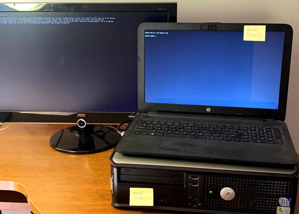
Each node needs a unique hostname, and each node must be able to resolve the name of all other nodes in DNS. The three nodes used for this article are micro1, micro2 and micro3.
Create the MicroK8s cluster
Begin with the same initial setup process for each K8s node. First configure networking, then install MicroK8s, and finally join the cluster.
Much of the installation for the first node may have been completed in part 2 of this series. If so, simply follow any steps below that have not yet been performed. If at any time system configuration changes appear to have created conflicts with MicroK8s, start over by simply removing the snap and related data to start over using the following command:
sudo snap remove microk8s --purgeConfigure networking
Kubernetes–and Multus in particular–expects all nodes to use the same network interface name; however, Ubuntu Server by default uses predictable interface names. As a result, each node likely will have a different network interface name. Netplan provides a solution to reliably rename the interface. The configuration below consistently renames each host’s primary interface to eth0 based on the interface’s MAC address.
Begin by identifying the MAC address for the interface to be used with K8s traffic. List all the interfaces on the node with the command ip a. Your results should look similar to the following (this laptop has both a wired and a wireless interface):
1: lo:  mtu 65536 qdisc noqueue state UNKNOWN group default qlen 1000
     link/loopback 00:00:00:00:00:00 brd 00:00:00:00:00:00
     inet 127.0.0.1/8 scope host lo
        valid_lft forever preferred_lft forever
     inet6 ::1/128 scope host
        valid_lft forever preferred_lft forever
 2: enp7s0:  mtu 1500 qdisc fq_codel state UP group default qlen 1000
     link/ether 58:20:b1:7f:32:10 brd ff:ff:ff:ff:ff:ff
     inet 192.168.1.21/16 brd 192.168.255.255 scope global eth0
        valid_lft forever preferred_lft forever
     inet6 fe80::5a20:b1ff:fe7f:3210/64 scope link
        valid_lft forever preferred_lft forever
 3: wlp13s0:  mtu 1500 qdisc noop state DOWN group default qlen 1000
     link/ether 40:b8:9a:1b:25:a3 brd ff:ff:ff:ff:ff:ff
Look for the interface labeled default, this is your primary network interface. Find the link/ether (i.e., MAC) address of this interface (58:20:b1:7f:32:10 in the example above).
Use this information to edit the current netplan configuration. The netplan configuration is normally the only file in the directory /etc/netplan; the default file for Ubuntu 20.04 server is /etc/netplan/00-installer-config.yaml. Modify your configuration similar to the following:
# This is the network config written by 'subiquity'
network:
  ethernets:
    lan:
      match:
        macaddress: 58:20:b1:7f:32:10
      set-name: eth0
      addresses:
        - 192.168.1.21/16
      gateway4: 192.168.1.1
      nameservers:
        addresses: [192.168.1.1]
  version: 2
This netplan configuration uses the match directive with the macaddress property to select the proper network adapter, then uses set-name to assign the interface the name eth0.
In addition to naming the network interface, this configuration also gives the interface a static IP address of 192.168.1.21, a default gateway of 192.168.1.1, and a DNS nameserver of 192.168.1.1.
After saving changes to the netplan configuration, a reboot for the interface name change to take effect.
DNS must also be set up properly for K8s nodes to locate each other. Although beyond the scope of this article, ensure that each node can resolve the IP address of other nodes in the cluster by host name.

Install MicroK8s on each node
With networking properly configured on your node, it’s time to install the MicroK8s snap. Also grant your user account permission to use microk8s commands:
sudo snap install microk8s --classic
sudo usermod -a -G microk8s $USER
sudo chown -f -R $USER ~/.kube
newgrp microk8s
Set up the primary node
Select one node in your cluster as a primary node. Normally this will be the first machine on which MicroK8s has been installed. Although all Kubernetes nodes in the cluster are essentially identical, one node serves as the master node which hosts the control plane. Other nodes join the cluster through this primary node.
On the primary node only, enable the DNS and Multus plugins used with the ROS 2 configuration:
microk8s enable multus dnsThese plugins do not need to be explicitly enabled on other cluster nodes, they will automatically be enabled as they join the cluster. This type of control plane work will shift to a standby node should the primary become unavailable.
Join the cluster
In order to add a second node to the cluster, first run the microk8s.add-node command on the master node. Output should look similar to the following:
From the node you wish to join to this cluster, run the following:
   microk8s join 192.168.1.21:25000/f3338b610728cffbca327fe12c7e78a5

If the node you are adding is not reachable through the default interface
    you can use one of the following:
     microk8s join 192.168.1.21:25000/f3338b610728cffbca327fe12c7e78a5
     microk8s join 10.1.224.64:25000/f3338b610728cffbca327fe12c7e78a5
This URL includes key material needed by the new node to join the cluster. Issue the join command on the new node to add it to the cluster:
microk8s join 192.168.1.21:25000/f3338b610728cffbca327fe12c7e78a5
Contacting cluster at 192.168.1.21
Waiting for this node to finish joining the cluster. ..
The microk8s.add-node command must be used to generate new key material each time a new node joins the cluster.
Use the command microk8s status to monitor the new node as it joins the cluster and configures necessary system services:
microk8s is running
high-availability: no
  datastore master nodes: 192.168.1.21:19001
  datastore standby nodes: none
addons:
  enabled:
    dns                  # CoreDNS
    ha-cluster           # Configure high availability on the current node
    multus               # Multus CNI enables attaching multiple network interfaces to pods
  disabled:
    ambassador           # Ambassador API Gateway and Ingress
    cilium               # SDN, fast with full network policy
...
Notice that the DNS and Multus plugins have been enabled as part of the process for joining the cluster.
Repeat this step to add a third K8s nodes to the cluster. Once the cluster contains three or more nodes, microk8s status will show that high-availability has been automatically enabled.
Explore the cluster
If deployments were configured on the master node before adding additional nodes, these should still be running on the master. However, if the cluster does not have a deployment configured yet, apply the ROS talker / listener configuration as described in part 2 of this series. With this initial set of running pods and containers, take a look at which nodes are actually running the pods. Then experiment with scaling the number of running pods, and draining a node before taking it out of service.
List pods by node
Begin by checking the status of available nodes with the command microk8s.kubectl get nodes. This command can be executed on any of the K8s nodes.
NAME     STATUS   ROLES    AGE     VERSION
micro2   Ready    <none>   3m      v1.19.2-34+1b3fa60b402c1c
micro1   Ready    <none>   5h      v1.19.2-34+1b3fa60b402c1c
micro3   Ready    <none>   2m1s    v1.19.2-34+1b3fa60b402c1c
In order to identify which K8s node hosts different pods, use the command
microk8s.kubectl get pods -o wideThis returns the state of the pods, along with their primary IP address and the node hosting the pod:
NAME                                     READY   STATUS    RESTARTS   AGE  IP            NODE     NOMINATED NODE   READINESS GATES
ros-talker-deployment-6c447f496c-vf6nx   1/1     Running   0          4m   10.1.222.70   micro1
ros-listener-deployment-575bfddd-czz9j   1/1     Running   0          4m   10.1.222.73   micro1
ros-talker-deployment-6c447f496c-hmzpw   1/1     Running   0          4m   10.1.222.66   micro1
Add more pods
The results above show that the first node in the cluster, micro1, still hosts all the pods in the cluster. However, scaling up the number of talkers creates new pods on the other nodes:
microk8s.kubectl scale deployment ros-talker-deployment --replicas=10Watch the output of microk8s.kubectl get all -o wide as these new pods start across different nodes.
Take a node out of service
Running pods should be removed from service before shutting down a node. This is known as draining the node; the following command drains all work off the micro3 node:
microk8s.kubectl drain micro3 --ignore-daemonsetsDaemonSet pods are ignored (if any exist) since they generally run on all nodes and cannot be migrated off a node.
Monitor the cluster as new pods are launched on micro1 and micro2while pods on micro3 are shut down:
node/micro3 already cordoned
WARNING: ignoring DaemonSet-managed Pods: kube-system/calico-node-skfr5, kube-system/kube-multus-ds-amd64-g98cc
evicting pod default/ros-talker-deployment-6c447f496c-b9wzj
evicting pod default/ros-talker-deployment-6c447f496c-hmzpw
evicting pod default/ros-talker-deployment-6c447f496c-t55pl
evicting pod default/ros-talker-deployment-6c447f496c-bcdws
evicting pod default/ros-talker-deployment-6c447f496c-mmt2s
pod/ros-talker-deployment-6c447f496c-b9wzj evicted
pod/ros-talker-deployment-6c447f496c-mmt2s evicted
pod/ros-talker-deployment-6c447f496c-hmzpw evicted
pod/ros-talker-deployment-6c447f496c-t55pl evicted
pod/ros-talker-deployment-6c447f496c-bcdws evicted
node/micro3 evicted
Notice that each new container refreshes and the talker counter resets. Once the node completes successfully, the command microk8s.kubectl get nodes shows the status of micro3 as SchedulingDisabled:
NAME     STATUS                     ROLES    AGE   VERSION
micro1   Ready                      <none>   2h    v1.19.3-34+a56971609ff35a
micro2   Ready                      <none>   2h    v1.19.3-34+a56971609ff35a
micro3   Ready,SchedulingDisabled   <none>   2h    v1.19.3-34+a56971609ff35a
Finally, when work on micro3 is complete, issue the command microk8s.kubectl uncordon micro3 to return the node to service.
Conclusion
We have a ROS system running across three different machines, and we’re able to distribute Kubernetes pods across all the machines. In the final post of this series, we’ll take a look at a few alternate configurations for our talker/listener setup to better understand how to troubleshoot your setup.

